
Converts thermal waste into electricity
CONTACT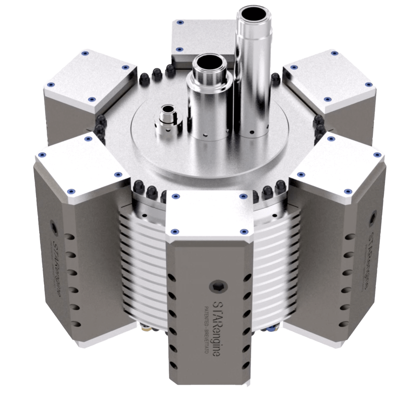
A new generation of patented Organic Rankine Cycle radial engines
Our Research and Development history on this project dates back to 2004, when we explored the energy balance of different technologies. We initially built and tested different types of expanders: scroll, screw and turbine to reach the conclusion, a few years later, that the reciprocating engine still was the simplest, most efficient and flexible solution for electricity generation from low grade sources.
A unique and groundbreaking solution for the environment
Our modified Organic Rankine Cycle expander operates under working conditions unparalleled by other turbines while maintaining unchallenged flexibility. Due to its unique features at a global level, research institutions and universities are currently involved in conducting studies on the StarEngine.


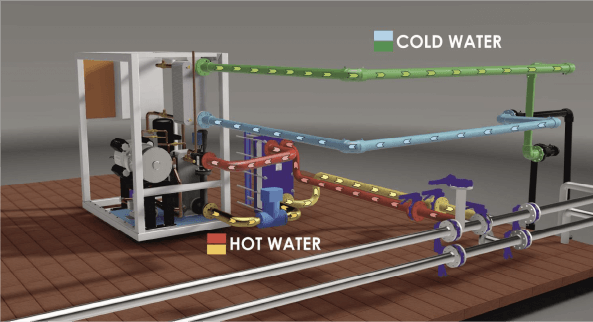
How it works:
On a simple principle of physics: the steam engine.
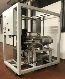
Our expander is a closed loop radial steam engine (a “star engine”) where a low boiling fluid (-26°C) is circulated inside instead of water.
The system is powered by means of hot water transferring thermal energy to a high-pressure compressed gas (up to 27 bar), which is injected into the piston chamber through our patented distribution system. The crankshaft, driven by our patented radial engine, spins an electric generator. Once expanded, the gas is condensed and then re-circulated through the system to repeat the cycle in a closed loop.
Patents and awards
Over several years of R&D and significant investments later we have been able to implement and fine-tune multiple unique solutions involving both the cycle and the technology. These innovative features have been patented worldwide and are reflected into the system’s outstanding performance and reliability.

Patent notice
The machine is protected by one or more of the following patents and patent applications:
IT 102016000080081
EP 17757889.5
US 11,060,404
IT 102016000080087
IT 1393264
IT 1410508
EP 2430306B1
IT 1416617
EP 2971619B1
BR 112015022225-0
RU 2633321
US 9,759,097
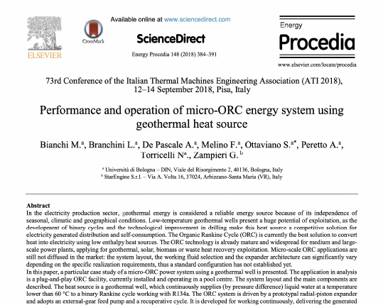
Scientific Publication University of Bologna
Features
- Efficiency
- Robustness
- Reliability
- Flexibility
- Wide areas of application
- Self-regulating
- Stable operation
- Easy to use
- Easy maintenance
- No parasitic power absorption

Thermal sources
- Heat sources: water, air, oil, fumes
- Low temperature geothermal sources range: 45°C to 150°C
- Industrial process cooling range: 45°C to 90°C
- Engine basement cooling range: 70°C to 88°C
- Cold sources: water, air
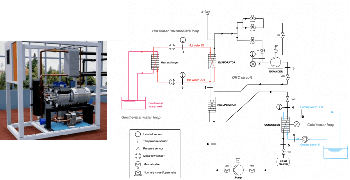
Schematic diagram
Efficiency
Efficiency is determined by the thermal jump between the hot source and the cold source, i.e. of a maximum-minimum pressure ratio, according to the criteria of calculation below:
The Carnot cycle
η =
T1-T2
T1
Efficiency
Thermodynamics indicates that the cycle achieving maximum efficiency is the Carnot cycle, and this ideal machine has been our focal point throughout the development of our expander
Schematic diagram
For a machine working between 70°C (343.15 K) and condensing at 25°C effective (298 K)
the theoretical maximum efficiency is the following:
η =
T1-T2
T1
η =
T1-T2
T1
η =
T1-T2
T1
Experimental testing under standard conditions resulted in a 7 to 11% range of net thermal efficiency, corresponding to 54% and 84% of the Carnot cycle.
Heat sources
Heat sources generally involve a hot fluid used in the production process on the client’s site, and where water is often the carrier fluid. The energy balance of the source, that it the thermal power, is calculated through a formula. Flow rates are generally expressed in m3/h or l/sec or l/min.

Schematic diagram
P (Kcal)= m x c x Δt
Δt in °C
c = 1
Kcal = 4.186 J
and with flow rate expressed as m3/sec
1h = 3600 sec
P (kW) = m x c x Δt x 1.16
Where
m = mass flow rate as m3/sec
c = specific heat of the water or glycol solution (1 to 0.7)
Δt = THERMAL JUMP between the inlet/outlet water temperatures in the exchanger
Example 1
Hot water
The thermal jump can be derived from a calculation with known values of volumetric flow rate and of power:
P=500 thermal kW
30 m3/h clean, glycolised-free water
Thermal jump Δt=
500
30 x 1,16
Δt= 14.36°C (K)
Assuming a 10% net thermal efficiency for the system, the obtainable power would be of 50 kW electric.
(see this section for product selection).
Example 2
Hot water
The volumetric flow of the pump can be derived from a calculation with known thermal power and by inputting the thermal jump value:
P=500 thermal kW
Pump flow rate in cubic metres h
Input thermal jump = 88-70=18 °C
m=
500
18 x 1,16
m = 23.94 m3/h
Example 3
Hot water
The available thermal power can be derived from a calculation with the measured volumetric flow and thermal jump:
m= 70 m3/h
Power calculation
Temperature difference (input-output) = 5°C
P= 70 x 1 x (5 x 1.16) P = 407 thermal kW
Example 4
Hot fumes gas recovery calculation
Chimney capacity: 2000 m3/h Approximate enthalpy for 1 m3 of air as 0.31 kcal/m3
Hot smoke at outlet 400°C
Hot smoke after heat recovery 150°C
Temperature difference: 250 °C
Recoverable thermal power =
2000
860 x 250 x 0.31
= 180 kW
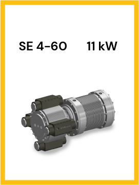
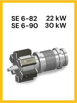
Product selection
The selection of the appropriate machinery should be based on four guiding principles:
- Thermal power of the heat source
- Thermodynamic coordinates at which the machinery is expected to operate
- Definition of the expected efficiency, taking into account gas evaporation and condensation temperatures (2/3 of the Carnot cycle functioning between the same isotherms)
- Calculation of the power output obtainable from the cycle
Determining gas evaporation temperatures
The reference temperatures are the actual ones. For example, if water is inlet at 85°C and outlet at 75°C, the average temperature (approximated for simplicity) is 80°C. The exchanger transfers power thorough partitions (walls) causing an inevitable thermal jump.
StarEngine utilizes only high quality components, which are oversized to factor in possible power and load losses.
For the exchangers, 3 to 5 degrees Kelvin are generally taken into consideration.
Back to the above example, the actual temperature in the exchanger would be between 75 and 77°C.
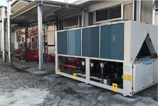
Determining gas condensation temperatures
Always with reference to actual temperatures, determining gas condensing temperatures is more complex than determining evaporation temperatures because of the different options available in terms of gas condensing technologies.
For example, direct cooling systems can be employed through the use of air exchangers, or systems using an intermediate fluid like water, or also hybrid systems. The selection should be performed with the assistance from an expert in thermodynamics, since choices can greatly influence performances. The same considerations also apply to the condensation system, except that thermal jumps in the condensation system could be very different. Pressure drops inside the exchangers are practically irrelevant thanks to the oversizing.
Example of condensation with tube bundle and cooling tower
By making a simplification, we could consider the temperature in the tower as being 6°C lower than the outer temperature due to the adiabatic expansion of the water. The thermal jump with an efficiently working condenser and with a good flow rate could be around 9°C. For example, with an average annual temperature of 11.4°C, we would consider an average condensing temperature of approximately 11.4 – 6 + 9 = 14.4°C.
Example
Assuming we have:
a hot source of 70 m3/h of water inlet at 75°C and outlet at 70°C
and a cold source of 70 m3/h of water inlet at 15°C and outlet at 20°C.
we calculate the heat output available to the system:
(ref. example 3)
Connection to the electricity grid
The engine is connected to a 4-pole 50/60 Hz, 400V Siemens asynchronous generator certified for operation in parallel with the grid.
The system is sealed and linked through 5 connectors (3-phase + neutral + ground) that must be connected to the power protection system selected by the customer in accordance with the requirements of the relevant network operator. The rotation speed is that fixed for a two-pole generator with positive slip.
Application Examples
- Food precessing plants
- Steel industry
- Chemical industry
- Plastic extrusion
- Injection mold cooling
- Paper mills
- Geothermal
- Metal processing and metal working plants
- Oil cooling
- Thermal waste from turbines and electrical machines
StarEngine in figures
If the ratio for electric generation from fossil fuels is the following:
One Tonne of Oil Equivalent (TOE) = 5350 kWh
If the machine generates 20 kWh electric over 8500 hours, we get:
20 x 8500 = 170,000 kWh
The amount of fuel used to produce this energy is:
170,000/5,350 = 31 tonnes of oil
Considering that 1liter of oil weighs 0.84 kilograms
31,000/0.84 = 36,000 litres
For every kWh electric, 2.55 kilograms of oil get burned.
CO2
For every kWh electric, 0.65 kilograms of carbon dioxide emissions are produced.
According to the above calculation,
170,000 kWh from fossil fuels would have generated:
170,000 x 0.65 = 110500 kg CO2 kilograms of CO2 emissions
Economic value
TEE (Energy Efficiency Certificates), also called white certificates, are recognized for each Tonne of Oil Equivalent.
White certificates are traded on the free market or through the grid operators.
Using an approximate value of 0.20 €/kWh, the following energy is generated:
170,000 x 0.20 = €34,000 per year
Factoring in current Carbon Tax values, the amount is: €42,500/year approximately.
Conclusions
The environmental benefits for each StarEngine machine are the following:
110 TONS of carbon dioxide emissions
36000 LITRES of fossil fuel
producing €34,000 per year

Converts thermal waste into ectricity